
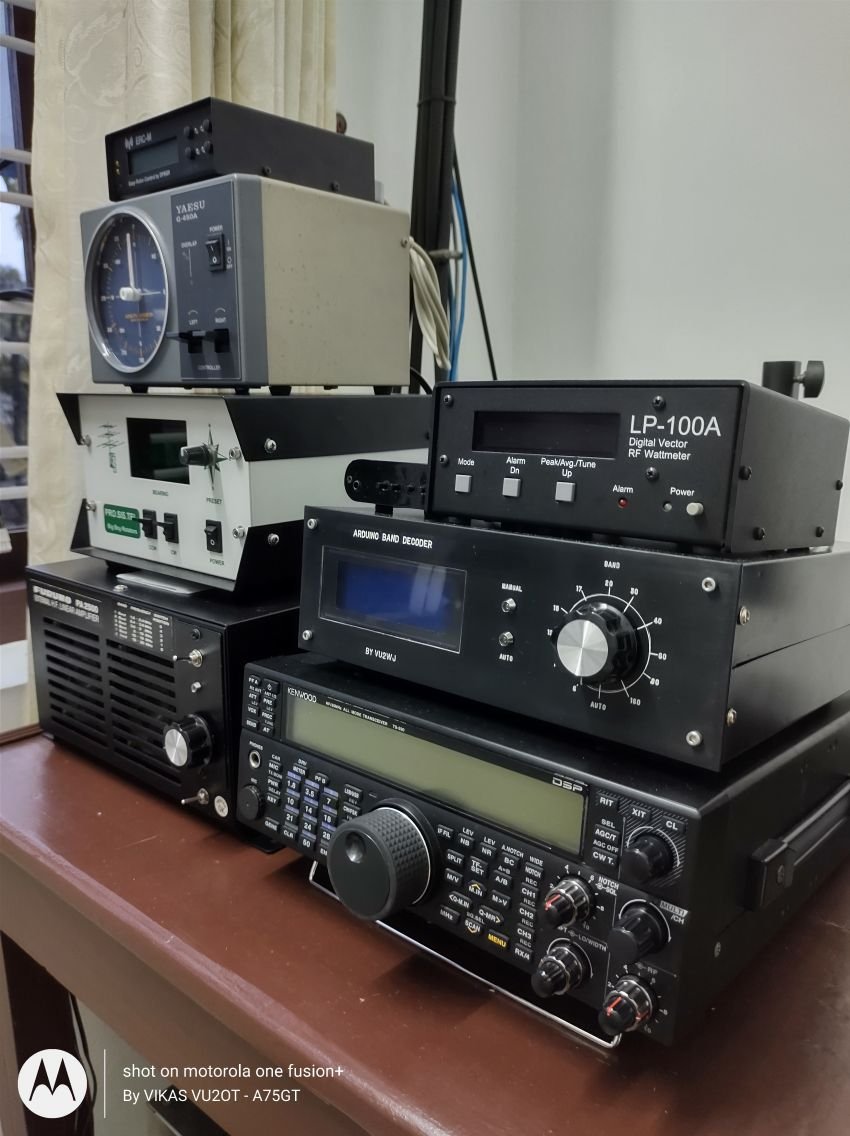
How the band decoder works
- TransceiverSends band or frequency data over its serial port.
- Arduino NanoReads the data through an RS-232 interface and shows the band on a 20×4 LCD.
- CD4514 + relay boardThe 4-to-16 line decoder drives a 16-channel relay module.
- Your stationAntenna switches, RX/TX filters, power amplifiers and transverters change band automatically.
The build


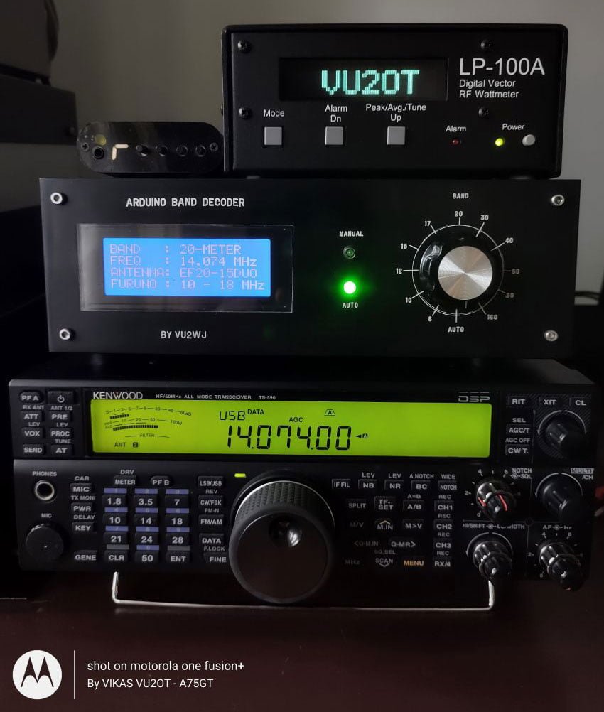
The firmware is based on the open-source band decoder code by OK1HRA (RemoteQTH), heavily modified, assembled and tested by VU2WJ to suit the needs of the VU2OT station. The front panel and the shack layout were designed by VU3YLI.
Everything sits in a 24 × 24 × 8 cm metal enclosure re-used from one of VU2WJ's oldest DDS VFO projects — chosen because it holds every part with room to spare for wiring. The front panel was moulded from 3 mm black acrylic sheet by a local vendor.
The layout on the right shows a typical installation: the decoder sits between the transceiver and the antenna switching, filters and amplifier, so a band change on the radio sets up the rest of the station.

Parts list
- Nano V3.0 development board (Arduino compatible)
- 16-channel relay module — DC 12 V, optocoupler protection, LM2576 power supply
- CD4514 4-bit latch / 4-to-16 line decoder IC (DIP-24)
- MAX3232 RS-232 to TTL converter module
- 20×4 LCD display with blue backlight
- SP12T rotary switch — 12 positions, with knob
- Connectors — DC, 9-pin DIN, mic and serial port
Driving a 400 W marine PA
The project also modifies a FURUNO PA2500 400 W solid-state marine amplifier, so the band decoder selects its low-pass filters automatically and switches between two antenna outputs.
Automatic or manual
The front panels of both the band decoder and the amplifier carry a 12-position rotary switch, so antennas and amplifier filters can follow the radio automatically or be set by hand.
1 Comment
Great work! This can be viewed on the following link:
https://hamphotos.com/post/2299?page=latest